Preventing Downtime: Auditing Heat Loss in Legacy Reheating Furnaces
Operating a legacy reheating furnace in today's high-tariff energy landscape is an exercise in managing hidden costs. In steel mills across Vietnam's industrial hubs—from Bình Dương to Hải Phong—reheating furnaces typically consume 60% to 70% of the entire plant's energy budget. Yet, thermodynamic audits reveal that older, PLC-controlled walking beam or pusher furnaces waste between 10% and 25% of their total fuel input directly through structural heat losses, air infiltration, and uninsulated piping.
At the same time, unexpected refractory collapse or furnace shell deformation is the leading cause of unplanned downtime in hot rolling mills. A single day of emergency shutdown can cost a mid-sized steel mill between $50,000 and $120,000 in lost production and repair expenses.
This technical guide, authored by Dr. Chen Wei (Chief Thermal Engineer at South Technology), explains how to execute a systematic heat loss audit on legacy reheating furnaces. It details the five key thermodynamic leakage pathways and explains how to implement modern thermal optimizations using the Zero CAPEX Energy Steward model to achieve a guaranteed 7% to 15% fuel savings while securing operational reliability.
1. Thermodynamic Audit: Identifying Furnace Heat Loss Pathways
Before investing in any physical upgrades, steel mills must establish a baseline of where heat is being lost. In an ideal reheating furnace, energy input from fuel combustion is transferred entirely into the steel billets. In legacy systems, a substantial portion of this energy escapes through alternative pathways.
The table below illustrates the typical distribution of heat losses in an unoptimized, legacy 150-tonne-per-hour walking beam reheating furnace:
| Heat Loss Pathway | Percentage of Total Fuel Input | Typical Physical Indicator | T80 Standard Corrective Action | Estimated ROI Payback (Zero CAPEX) |
|---|---|---|---|---|
| Refractory Wall & Roof Radiation | 4.0% – 8.0% | Shell temperatures > 95°C, visible shell deformation | Multi-layer ceramic fiber modules + high-emissivity coating | Immediate (Self-Funded) |
| Air Infiltration & Flue Gas | 5.0% – 12.0% | Flame licking, negative draft pressure, excessive scale | AI-driven pressure control + mechanical door seal replacement | Immediate (Self-Funded) |
| Water-Cooled Skid Pipes | 3.0% – 6.0% | Elevated cooling water discharge temperatures | Dual-layer pre-shaped fiber pipe insulation wrapping | Immediate (Self-Funded) |
| Combustion & Burner Wear | 4.0% – 10.0% | Misaligned flame profile, high O₂ in exhaust gases | AI predictive stoichiometric control + burner alignment | Immediate (Self-Funded) |
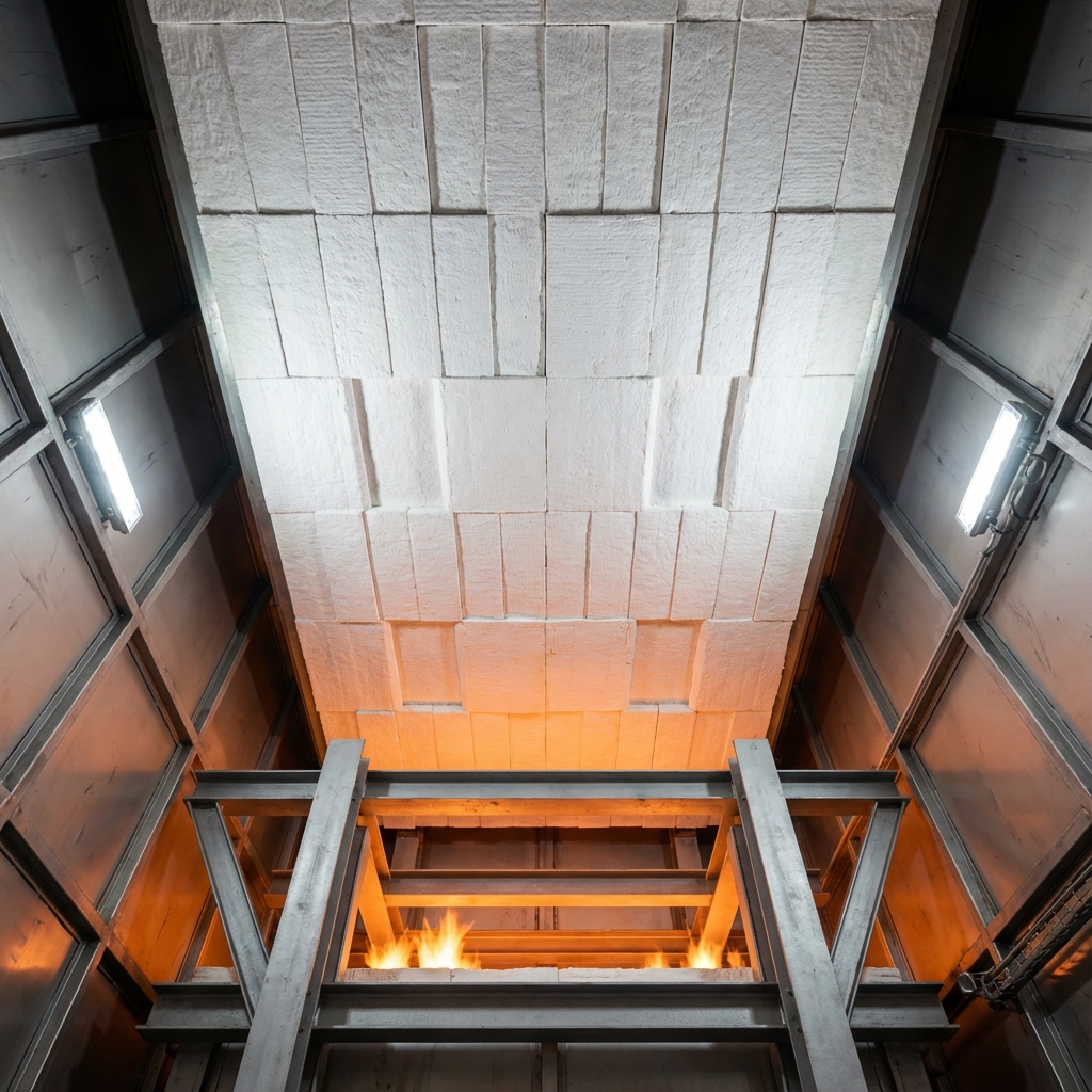
Figure 1: High-efficiency ceramic fiber roof installation replacing traditional heavy castable refractory walls
2. Technical Module 1: Refractory Lining Degradation & Insulation Audit
The Problem: Castable Aging and Thermal Bridging
Traditional reheating furnaces utilize heavy castable refractories or fireclay bricks. Over 3 to 5 years of continuous thermal cycling (heating to 1,250°C and cooling during maintenance), these materials suffer from thermal shock, leading to cracking, spalling, and eventual structural collapse.
As the refractory lining degrades, the heat transfer rate through the furnace wall increases. This leads to:
- Elevated furnace shell temperatures, sometimes exceeding 120°C (well above the safe B2B industry limit of 80°C).
- Rapid steel shell oxidation and warping, requiring expensive structural repairs.
- Severe working environment conditions for operators nearby.
The T80 Solution: Multi-Layer Ceramic Fiber Modules & High-Emissivity Coatings
Under the T80 Technical Roadmap, we replace heavy castables with pre-assembled ceramic fiber modules (anchored with heat-resistant alloys) combined with a high-emissivity functional coating applied directly to the hot face.
Ceramic fiber has a thermal conductivity that is 75% lower than traditional firebrick. The high-emissivity coating acts as a thermal mirror, reflecting infrared radiation back into the heating chamber rather than allowing it to penetrate the refractory wall.
"By replacing degraded castable brickwork with multi-layer ceramic fiber modules, we reduce the heat storage capacity of the furnace walls by 80%. This not only cuts radiation losses but allows the furnace to heat up and cool down significantly faster, improving operational agility." — Dr. Chen Wei, Chief Thermal Engineer, South Technology
Thermodynamic Impact: By upgrading the roof and walls, shell temperatures are brought down below 75°C, reducing refractory-related heat losses by 45% to 60%. This translates directly to a 3.5% reduction in gas consumption while preventing structural steel deformation.
3. Technical Module 2: Air Infiltration, Pressure Control & Door Seal Wear
The Problem: The "Chimney Effect" and Seal Deterioration
Furnace doors are opened and closed hundreds of times a day to charge and discharge billets. Over time, the mechanical seals and fiber curtains degrade due to high-temperature exposure and physical friction.
When seals fail, two main issues occur depending on furnace pressure:
- Positive Pressure (Flame Licking): Hot combustion gases escape through the gaps, damaging the door frame, sensor cables, and lifting mechanisms.
- Negative Pressure (Cold Air Infiltration): If the draft control damper is set too high, cold ambient air is sucked into the furnace. This cold air cools the billets and combustion gases, forcing the burners to fire harder to maintain temperature setpoints.
Furthermore, cold air introduces excess oxygen, which reacts with the hot steel to create iron oxide scale. Scale loss not only wastes valuable steel (up to 1.5% of total billet weight) but damages the furnace hearth.
The T80 Solution: Smart Pressure Control and Active Seals
The T80 standard implements a dual-action correction strategy:
- Active Mechanical Seals: High-resiliency ceramic fiber ropes and pneumatically-pressed door clamps that maintain a tight seal even as the furnace expands and contracts.
- AI-Driven Draft Regulation: Variable frequency drives (VFD) on the exhaust dampers, controlled by real-time pressure sensors. The AI maintains a micro-positive pressure (+10 Pa to +15 Pa) at the hearth level, completely eliminating cold air infiltration.
"A furnace pressure deviation of just 5 Pascals can increase fuel consumption by 4%. AI-driven pressure tracking ensures the draft control adjusts instantly to door movements, sealing the heat inside where it belongs." — Zhang Liang, Senior Process Engineer, South Technology
📋 B2B Resource: Furnace Optimization Guide Struggling to balance fuel efficiency with scale loss in your hot rolling mill? Download our latest guide for B2B steel mills: Download Free Furnace Audit Checklist → | View T80 Case Studies →
4. Technical Module 3: Water-Cooled Skid Pipe Energy Leakage & Insulation Wraps
The Problem: Water Cooling as a Heat Sink
In walking beam reheating furnaces, the steel billets are supported and transported by a network of water-cooled skid pipes. Because these steel pipes are continuously circulated with cold water to prevent structural bending under load, they act as massive thermal heat sinks inside the 1,250°C furnace.
If a skid pipe is uninsulated or if the insulation has fallen off, the heat loss to the cooling water is immense. A single meter of uninsulated water-cooled pipe can absorb more heat than 10 square meters of insulated furnace wall. This leads to:
- Excessive heat carry-away in the cooling water, requiring larger cooling towers.
- "Cold spots" or "skid marks" on the bottom of the steel billets, which cause rolling defects and damage the rolling mill stands.
The T80 Solution: Dual-Layer Pre-Shaped Pipe Insulation
We apply a dual-layer pre-shaped refractory insulation wrap secured with high-alloy wire mesh and anchors.
The inner layer consists of a high-temperature ceramic fiber blanket that cushions the pipe against vibration, while the outer layer is a high-strength refractory block designed to resist physical impact from scale and burner gas flow.
Audit Checklist for Skid Pipe Insulation:
- Insulation Coverage: Ensure >98% of all water-cooled pipe surfaces are covered.
- Anchor Integrity: Check for weld failures on alloy anchors during every monthly shutdown.
- Discharge Temperature Tracking: Monitor cooling water inlet/outlet temperature differences. A delta exceeding 15°C indicates localized insulation failure.
Implementing dual-layer wraps reduces the heat loss to cooling water by up to 85%, which improves billet temperature uniformity and saves 2.5% to 4.5% in fuel.
5. Technical Module 4: Burner Combustion Efficiency & Air-Fuel Ratio Misalignment
The Problem: Off-Stoichiometric Combustion
Industrial burners deteriorate over time. Coal tar, gas impurities, and thermal fatigue cause burner nozzle erosion, leading to misaligned flames and improper air-fuel mixing.
If the air-fuel ratio is incorrect:
- Excess Air (Fuel Waste): Unneeded combustion air is heated to 1,200°C and exhausted through the chimney, carrying valuable heat away.
- Deficient Air (Unburned Fuel): Incomplete combustion occurs, resulting in CO emissions, black smoke, and wasted chemical energy.
Most legacy mills run on a fixed air-fuel curve set years ago. However, fuel gas calorific values and ambient air temperatures change daily, meaning a static curve is always operating sub-optimally.
The T80 Solution: AI Predictive Stoichiometry
Our Smart Combustion Control System utilizes real-time laser flue gas analyzers ($O_2$ and $CO$) installed at the zone crossovers.
The AI algorithm continuously calculates the optimal combustion air volume for every burner zone based on real-time gas quality and heating requirements. Instead of waiting for a manual adjustments, the control loops tune the air valves every 3 seconds, maintaining the excess air coefficient at an ultra-low 1.05 to 1.10.
For mills exporting to regions affected by carbon pricing, this optimization is critical. It lowers direct emissions while generating verified data for compliance reporting under frameworks like EU CBAM.
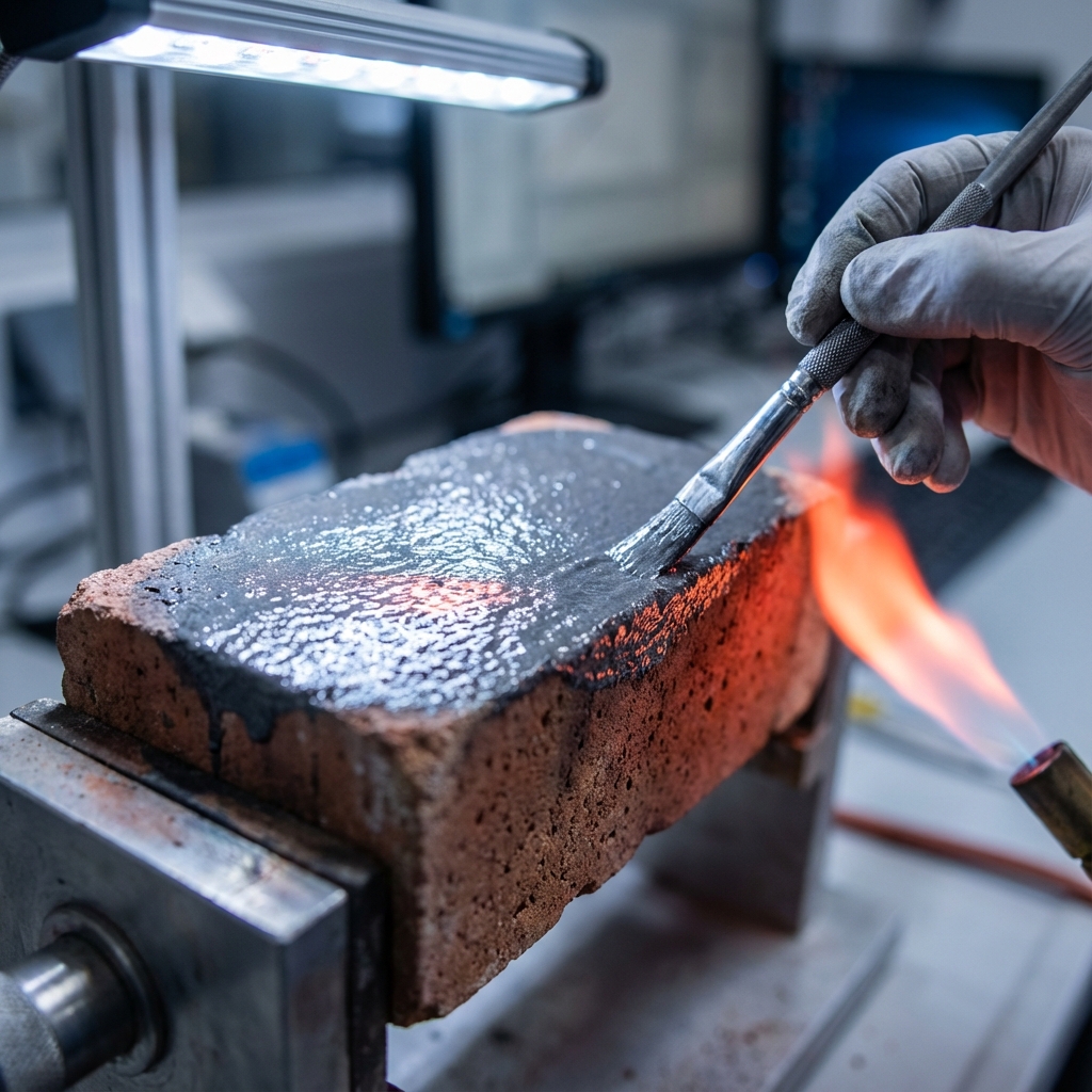 Figure 2: Interior application of high-emissivity refractory coatings to optimize radiant heat transfer
6. Technical Module 5: Thermal Imaging, Digital Twins & Predictive Energy Auditing
The Problem: Blind Operation
Traditional operators adjust zone temperatures based on thermocouples installed in the furnace roof. However, thermocouples only measure gas temperature at a single point; they do not show the actual heat absorption of the billets or the physical hot spots on the furnace shell.
The T80 Solution: Real-Time Infrared Thermography & Digital Twins
We install high-resolution infrared cameras inside the heating chamber and on the external furnace shell. The thermal imaging data is fed into a Digital Twin model that simulates the temperature field of the furnace and the internal stress of the steel billets in real-time.
The system provides:
- Shell Heat Loss Mapping: Automatic alerts when external shell temperatures exceed 80°C, indicating localized refractory degradation.
- Billet Temperature Uniformity: Real-time tracking of billet core and surface temperatures to ensure optimal rolling conditions without overheating.
- Predictive Maintenance: Detecting structural damage weeks before it causes an unplanned shutdown, allowing repairs to be scheduled during routine maintenance.
Furnace Thermal Auditing
A comprehensive engineering process that measures all energy inputs and outputs of an industrial heating system. By conducting mass and energy balance calculations, thermal audits isolate heat loss pathways (wall radiation, flue gas enthalpy, cooling water carry-away, scale reaction) and provide a quantitative roadmap for energy-saving retrofits.
7. The Zero CAPEX Energy Steward Model: De-risking Your Upgrade
Upgrading a reheating furnace’s refractory lining, skid pipe insulation, and burner control systems represents a capital expenditure of $300,000 to $600,000. In a volatile steel market, securing budget for energy-saving projects can be difficult.
EcoReheating’s Energy Steward Model removes this barrier:
- 100% Upfront Investment: EcoReheating pays for all equipment, software, installation, and engineering.
- Performance-Based Returns: The steel mill pays nothing upfront. Once the project is live, the fuel savings are measured against a verified baseline using international protocols (IPMVP).
- Shared Savings: The mill pays EcoReheating a pre-agreed share of the actual, verified energy savings. If there are no savings, the mill pays nothing.
This model aligns incentives perfectly. We only succeed if your furnace runs more efficiently and reliably.
"Many steel mills delay critical furnace maintenance because of CAPEX constraints, only to pay double in emergency downtime and fuel bills. The Energy Steward program converts these wasted energy dollars into a fully-funded upgrade." — Li Minghua, Project Director, South Technology
Ready to Eliminate Thermal Waste?
Are you unsure how much energy your reheating furnace is losing? Our engineering team will analyze your fuel usage, production capacity, and shell temperature data to generate a customized Furnace Efficiency Audit Report—fully funded by EcoReheating.
Request Your Free Thermal Assessment →
No commitment required. Limited to 2 assessments per month for mills with capacity exceeding 100,000 tpy.
Dr. Chen Wei
Chief Thermal Engineer, South Technology
Dr. Chen has over 15 years of experience in industrial furnace optimization and has led energy efficiency upgrades for over 300 production lines globally. He is a primary contributor to the CISA T80 industrial efficiency standard.
Quick ROI Estimator
See how much you could save using our Energy Steward Model
Based on typical 11% fuel efficiency optimization.
Get Verified ROI AuditFrequently Asked Questions
Q.What are the most common signs of severe heat loss in an industrial reheating furnace?
The most common visual and thermal indicators include hot spots on the furnace shell (exceeding 85°C), visible gas escape or flame licking around doors, negative draft drawing cold air through charging ports, and rapidly deteriorating water-cooled skid pipe insulation. A professional thermal imaging survey can instantly reveal these losses.
Q.How does air infiltration affect the combustion efficiency inside the furnace?
Cold air drawn into the furnace through worn seals and doors lowers the localized temperature of the combustion zone. To compensate, burners must consume more fuel to maintain the temperature setpoint. Additionally, excess oxygen increases scale loss (oxidation) on the steel billet surface, which reduces overall yield.
Q.Can a steel mill upgrade its refractory lining without shutting down operations for months?
Yes, by utilizing pre-assembled ceramic fiber modules instead of traditional castable refractory linings, installation time is reduced by up to 60%. These upgrades can often be scheduled during planned maintenance windows, minimizing production disruptions.
Q.Why is the Zero CAPEX Energy Steward model beneficial for legacy furnace retrofits?
Retrofitting a legacy reheating furnace can require an investment of $300,000 to $600,000. Under the Energy Steward model, EcoReheating covers all hardware, software, installation, and engineering costs upfront. The mill pays only a percentage of the verified energy savings, meaning the project is fully self-funded from day one.
Dr. Chen Wei
Chief Thermal Engineer, South Technology
Dr. Chen has over 15 years of experience in industrial furnace optimization and has led energy efficiency upgrades for over 300 production lines globally, specializing in the T80 extreme efficiency standard.